Troubleshooting: Warping in FDM Production Parts
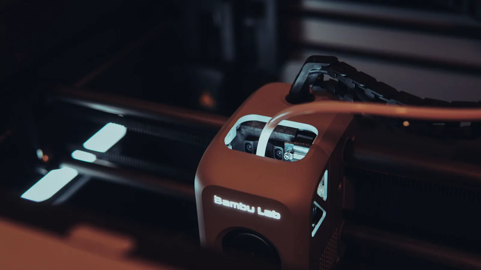
FDM warping causes curling, lifting, and delamination in service bureau parts. It usually stems from cooling rates, bed adhesion, or material moisture. This guide covers symptoms, causes, and fixes for FDM troubleshooting.
- FDM warping usually results from uneven cooling, poor bed adhesion, or material moisture.
- Service bureau parts often fail due to missing process controls, not just bad parts.
- Check first layer adhesion, bed temperature, and material drying before blaming the machine.
- Prevention requires specifying cooling profiles and adhesion methods in the RFI.
FDM Warping in Outsourced Parts: Causes, Checks, and Prevention
FDM warping is a common defect in outsourced parts. It shows up as curling corners, lifting edges, or delamination between layers. When this happens, the part fails inspection or needs rework.
The problem rarely starts with the printer itself. It usually appears when cooling rates, bed adhesion, or material handling fall outside the design intent. This is especially true for functional parts made from engineering resins.
What does FDM warping look like in service parts
Warping presents in a few distinct ways. The most common symptom is corner curling, where the edges lift off the build plate. Another sign is a domed bottom surface, often called a “saddle” shape. In severe cases, the part detaches from the bed entirely.
You can also see delamination. The part looks fine on the outside, but layers separate internally. This weakens the part and makes it brittle. Inspectors usually flag this during dimensional checks or break tests.
In service bureau work, these defects often appear after assembly. A bracket may fit the mating part during inspection but fail once it is installed. The stress from mounting forces exposes the internal weakness created by the print. Engineers frequently discover this during the first field trial, long after the parts have been packed and shipped.
Corner curling is usually the first sign of trouble. The corners are the first to cool because they have the most exposed surface area. As the plastic contracts, the tension pulls the edge upward. If the part is small, this curl may only lift the corner by a fraction of a millimeter. If the part is large, the lift can be significant enough to prevent it from sitting flat on a machine surface.
Saddle shape is a more subtle but equally damaging defect. The bottom of the part curves downward in the center while the edges remain flat. This often happens when the bed is not level or when the material shrinks unevenly. The part may look straight from the side, but a flatness check with a dial indicator will show the deviation.
Delamination is the hardest to spot. The part may pass a visual check and even a basic dimensional check. The layers are intact on the surface, but the bond between them has failed. This usually shows up during load testing or when the part is exposed to vibration. The part does not break cleanly. It fractures along the layer lines, leaving a stepped surface.
Common causes of FDM warping
| Symptom | Likely cause | What to do |
|---|---|---|
| Corner curling | Uneven cooling between edges and center | Add cooling fans or increase cooling rate for overhangs |
| Lifting edges | Poor bed adhesion or insufficient first layer heat | Increase bed temperature or apply adhesive |
| Delamination | Internal stress from fast cooling | Slow cooling for thick sections or add infill |
| Saddle shape | Material shrinkage during cooling | Level the bed and adjust retraction settings |
| Brittle part | Material moisture absorption | Dry the filament in a controlled environment |
| Warped thin walls | High cooling rates on thin features | Reduce fan speed or modify the part design |
The first step in FDM troubleshooting is matching the symptom to the cause. A curled corner is not the same problem as an internal break. Treating them the same way wastes time.
Corner curling and lifting edges often share a root cause but require different fixes. Curling is usually driven by cooling asymmetry. Lifting is usually driven by adhesion failure. If you increase bed temperature to fix curling, you may make the adhesion worse. If you increase fan speed to fix lifting, you may make the curling worse. The process requires isolating the variable that is actually failing.
Delamination is a material and cooling issue. It is rarely caused by the bed. If the part has internal layer separation, checking the bed surface is a waste of effort. The problem is in the thermal gradient inside the part. The top layers are cooling faster than the bottom layers, creating a stress that exceeds the bond strength between the layers.
Saddle shape is a geometry and bed level issue. It is often confused with general warping. If the part is flat in the corners but curved in the center, the bed is likely not level. If the entire bottom surface curves, the material is shrinking unevenly. The fix for a level bed is mechanical. The fix for shrinkage is thermal.
Brittle parts are almost always a moisture problem. The filament has absorbed water from the air. During printing, the water flashes to steam in the hot nozzle. This creates voids and weakens the polymer structure. The part may print without visible defects but will shatter under minimal load.
Warping thin walls is a design and cooling issue. Thin features cool too fast. The material solidifies before it can bond properly with the adjacent layer. This creates a brittle wall that warps as it cools. The fix is to reduce the cooling rate or to change the geometry. In some cases, the part needs a thicker wall or a rib to distribute the stress.
How cooling rates drive FDM warping
Plastic contracts as it cools. If the top layers cool faster than the bottom layers, stress builds inside the part. The edges cool before the center, so they pull inward and lift.
This is a major issue for service bureau work. Many bureaus use standard cooling profiles without adjusting them for the specific part geometry. A thick block and a thin bracket need different fan settings. A part with complex overhangs needs a different profile than a part with flat surfaces.
If you order a part and it curls, ask the bureau for their cooling profile. If they cannot provide it, the process is not controlled. A controlled process documents fan speeds, layer times, and ambient temperature.
Cooling profiles are usually defined in the slicer software. The profile controls when the fan turns on, how much air it blows, and how the air is directed. A standard profile might use a constant fan speed for the entire print. A controlled profile changes the fan speed based on the layer height and the geometry of the feature being printed.
For thick sections, the fan should be off or at a low speed. The material needs time to cool slowly so the internal stress remains low. For thin overhangs, the fan should be at a high speed. The overhang needs to solidify quickly to support its own weight. If the profile does not change, both problems occur. Thick sections warp. Thin overhangs droop.
Layer time is another factor. If the printer is slow, the material stays hot longer. This can reduce warping but increase the chance of overhang drooping. If the printer is fast, the material cools quickly. This reduces drooping but increases warping. The printer speed is part of the cooling profile. It must be documented.
Ambient temperature matters too. A print room at 20 degrees Celsius behaves differently from a print room at 30 degrees Celsius. The air temperature affects how fast the layers cool. If the room temperature changes during the print, the cooling profile changes. This is why controlled environments are needed for critical parts.
Bed adhesion and first layer quality
Warping starts at the bed. If the first layer does not grip the plate, the rest of the part has nothing to hold it down. This is common when the bed is not level or when the first layer temperature is too low.
Service bureaus often use a variety of bed surfaces. Some use PEI sheets, others use textured glass. Each surface reacts differently to the material. A part that prints well on PEI may lift on glass if the temperature is off.
Check the first layer carefully. The lines should be flat and slightly squished. If they look raised or stringy, the adhesion is weak. If they look flat but not fused, the temperature is too low. Both conditions invite warping.
The first layer is the foundation of the part. It must bond to the bed. It must also bond to the second layer. If the first layer is too hot, it may stick to the bed but not fuse to the next layer. If it is too cold, it may not stick to the bed. The temperature window is narrow. It varies by material and by bed surface.
Bed leveling is a mechanical issue. If the bed is not level, the first layer thickness varies across the build surface. In the low spots, the layer is too thick. In the high spots, the layer is too thin. The thin spots may not bond. The thick spots may warp. A level bed ensures a uniform first layer.
Bed surface texture is a chemical and physical issue. PEI is smooth and non-stick. It requires higher temperatures to bond. Textured glass is rough and sticky. It requires lower temperatures. If the bureau switches bed surfaces without adjusting the temperature, the adhesion changes. This is a common cause of inconsistent parts.
Adhesives can help. Glue sticks, hairspray, or commercial adhesives can improve bed adhesion. They fill the gaps between the bed and the first layer. They increase the contact area. They also increase the shear strength of the bond. However, they add a step to the process. They must be applied correctly. If they are not used, the adhesion relies on the bed surface alone.
Material moisture and storage
Filament absorbs moisture from the air over time. When the moisture hits the nozzle during printing, it creates steam bubbles. These bubbles weaken the bond between layers and cause delamination.
Engineering materials like nylon and PETG are especially sensitive. They need to be dried before printing and stored in a dry environment. A service bureau that does not control humidity for its materials will produce inconsistent parts.
Ask the bureau how they store their filament. Do they use a dry box? Do they have a climate-controlled room? If the answer is vague, assume the material may be compromised.
Moisture absorption is a time-based process. Filament absorbs water as long as it is exposed to the air. The rate of absorption depends on the material, the ambient humidity, and the packaging. A sealed bag of filament absorbs moisture slowly. An opened bag absorbs it quickly. A bag left open for a week may be too wet to print.
Drying is a controlled process. The filament is heated to a specific temperature for a specific time. The heat drives the water out of the polymer. The temperature must be high enough to remove the water but low enough to avoid degrading the polymer. The time must be long enough to dry the core of the filament.
Storage is equally important. Dried filament must be stored in a dry environment. A dry box with desiccant works well. A climate-controlled room with low humidity also works. If the filament is stored in a normal room, it will reabsorb moisture. The drying process is only temporary unless the storage is controlled.
Material handling is a weak point in many service bureaus. Filament is often stored in a cabinet or on a shelf. It is not always dried before printing. It is not always tracked for storage time. This creates variability. One batch of parts may be dry. The next batch may be wet. The defect rate changes from batch to batch.
Prevention tips for FDM production parts
- Specify the adhesion method in the drawing. State whether you need a glue stick, PEI sheet, or textured plate.
- Request the cooling profile in the quote. Ask for fan speed percentages and layer time data.
- Define the material drying procedure. Require a dry box or climate control for hygroscopic materials.
- Provide a test part before full production. This catches warping before you order hundreds of units.
- Inspect the first layer. Reject parts where the bottom layer is not flat and fully adhered.
These steps turn FDM troubleshooting from a reactive process into a controlled one. You are not guessing at the problem. You are checking the data.
Specifying the adhesion method removes ambiguity. The bureau knows what surface to use. It knows what temperature to set. It knows what adhesive to apply, if any. The drawing becomes a process instruction, not just a geometry description.
Requesting the cooling profile gives you visibility into the process. You can review the settings. You can compare them to your own test data. You can identify mismatches before the part is printed. This is more effective than inspecting the finished part.
Defining the drying procedure controls the material. The bureau must dry the filament before printing. It must store the filament in a controlled environment. It must document the drying time and temperature. This ensures the material is in the correct state when it enters the printer.
Providing a test part reduces risk. The test part is printed under the same conditions as the production run. It is inspected for the same defects. If the test part fails, the process is adjusted before the full run. If the test part passes, the process is likely stable for the full run.
Inspecting the first layer catches early failures. The first layer is the easiest to inspect. It is visible. It is accessible. It is the foundation of the part. If the first layer is weak, the part will fail. Rejecting parts with bad first layers prevents downstream defects.
When to reject a service bureau part
Sometimes the part cannot be fixed. If the warping is severe, the part may be unusable. In that case, the dispute belongs in the quality record, not in a casual email.
Review the RFI documents. Did you specify the material and the application? Did the bureau confirm the process in writing? If the documents are clear and the part failed, the burden is on the bureau to explain.
Use the defect as a data point. Document the failure mode. Send it back with photos and a note. This builds a record that helps in future negotiations or audits.
Rejection is a decision based on the specification. If the part does not meet the specification, it is rejected. The reason for rejection is not the cause of the defect. The reason is that the part does not meet the requirements. This distinction matters. It keeps the focus on the outcome, not the process.
The RFI documents are the baseline. They define the material, the geometry, the tolerances, and the functional requirements. They also define the process, if specified. If the documents are clear, the bureau has a reference to check against. If the documents are vague, the dispute is harder to resolve.
The burden of proof shifts when the documents are clear. If the part fails and the documents are clear, the bureau must explain why it failed. It must provide data. It must provide the cooling profile, the bed temperature, the material lot, and the drying record. If it cannot provide this data, the process is not controlled.
A casual email is not a quality record. It is not traceable. It is not auditable. It is not a basis for a claim. A quality record is a formal document. It includes the part number, the lot number, the date, the defect description, and the photos. It is stored in the quality system. It is part of the record.
How to write a defect report
A good defect report is short and factual. Include the part number, the lot number, and the date of delivery. Add photos of the defect. State the symptom clearly.
Example: Part P-102, Lot 45, received October 2026. Corner curling on the left side. First layer not adhered to the bed. Bed temperature set to 70 degrees Celsius.
Do not guess the cause in the report. Let the bureau analyze the process. Your job is to describe what you see. They are responsible for finding out why it happened.
The defect report is a communication tool. It tells the bureau what went wrong. It does not tell the bureau why it went wrong. The cause is the bureau’s responsibility. The report is the customer’s responsibility.
Photos are critical. They show the defect. They show the location of the defect. They show the scale of the defect. A photo of the whole part shows the context. A photo of the close-up shows the detail. Both are needed.
The symptom is the observation. The cause is the explanation. The report contains the symptom. The bureau provides the cause. This separation of roles is clear. It prevents disputes. It keeps the focus on the data.
The report should be objective. It should not use words like “bad” or “poor.” It should use words like “curling,” “not adhered,” “delaminated.” These words describe the condition. They do not judge the process. The judgment is made after the cause is identified.
Final checks before ordering
Before you send a new part to a service bureau, run through this list. Confirm the material is available and dry. Check the drawing for features that are prone to stress. Verify the bed type is compatible with the material.
If the part is critical, order a sample. Test it under load. Check the dimensions. Only then commit to the full run. This prevents a batch of bad parts from sitting in your inventory.
FDM warping is a solvable problem. It requires data, not guesswork. Control the cooling, the bed, and the material, and the defect disappears.
Material availability is a simple check. The bureau must have the material in stock. It must be within its shelf life. It must be dry. If the material is not available, the part cannot be printed. If the material is not dry, the part may fail.
Drawing review is a design check. The drawing shows the geometry. The geometry determines the cooling. It determines the adhesion. It determines the stress. If the drawing has features that are prone to warping, the process must be adjusted. If the drawing is changed, the process must be reviewed.
Bed compatibility is a process check. The bed must be compatible with the material. PEI is good for many materials. Textured glass is good for others. Smooth glass is good for a few. The bed must match the material. If the bed is not compatible, the adhesion will be poor.
A sample is a risk reduction step. It is expensive. It is time-consuming. It is not always practical. But for critical parts, it is necessary. The sample is printed under the same conditions as the production run. It is inspected for the same defects. It is tested for the same functions. If the sample fails, the process is adjusted. If the sample passes, the production run is likely to pass.
Testing under load is a functional check. The part must work in its application. It must handle the forces. It must handle the vibrations. It must handle the temperature. If the part fails under load, it will fail in service. The sample test catches this failure before the full run.
Dimensional checks are a quality check. The part must meet the tolerances. It must fit the mating parts. It must seat on the surfaces. If the dimensions are out of tolerance, the part is rejected. The dimensional check is part of the sample inspection. It is not optional.
The final check is the decision. The data is collected. The sample is tested. The process is controlled. The decision is made. If the decision is to proceed, the full run is released. If the decision is to stop, the process is adjusted. This decision is based on data, not hope.
Frequently asked questions
Can FDM warping be fixed after printing?
Not usually. Warping changes the part geometry and weakens the material. You can sometimes flatten it with heat and pressure, but the structural integrity is gone.
What is the best bed material for FDM warping prevention?
PEI sheets work well for most engineering materials. They provide a smooth surface and good adhesion. Textured glass is better for materials that need mechanical grip.
How do I know if my service bureau controls their process?
Ask for their cooling profile, bed temperature settings, and material drying procedure. If they cannot provide this data, their process is likely not controlled.
Does FDM warping affect all materials equally?
No. Nylon and PETG are highly susceptible due to moisture absorption. ABS is also prone to warping due to high shrinkage. PLA is generally more forgiving.
Should I always order a test part?
Yes, for new designs or new materials. A test part costs little and saves a large batch of bad parts. It also gives you data to verify the process before full production.