Buyer’s Guide: DfAM Software for Engineers
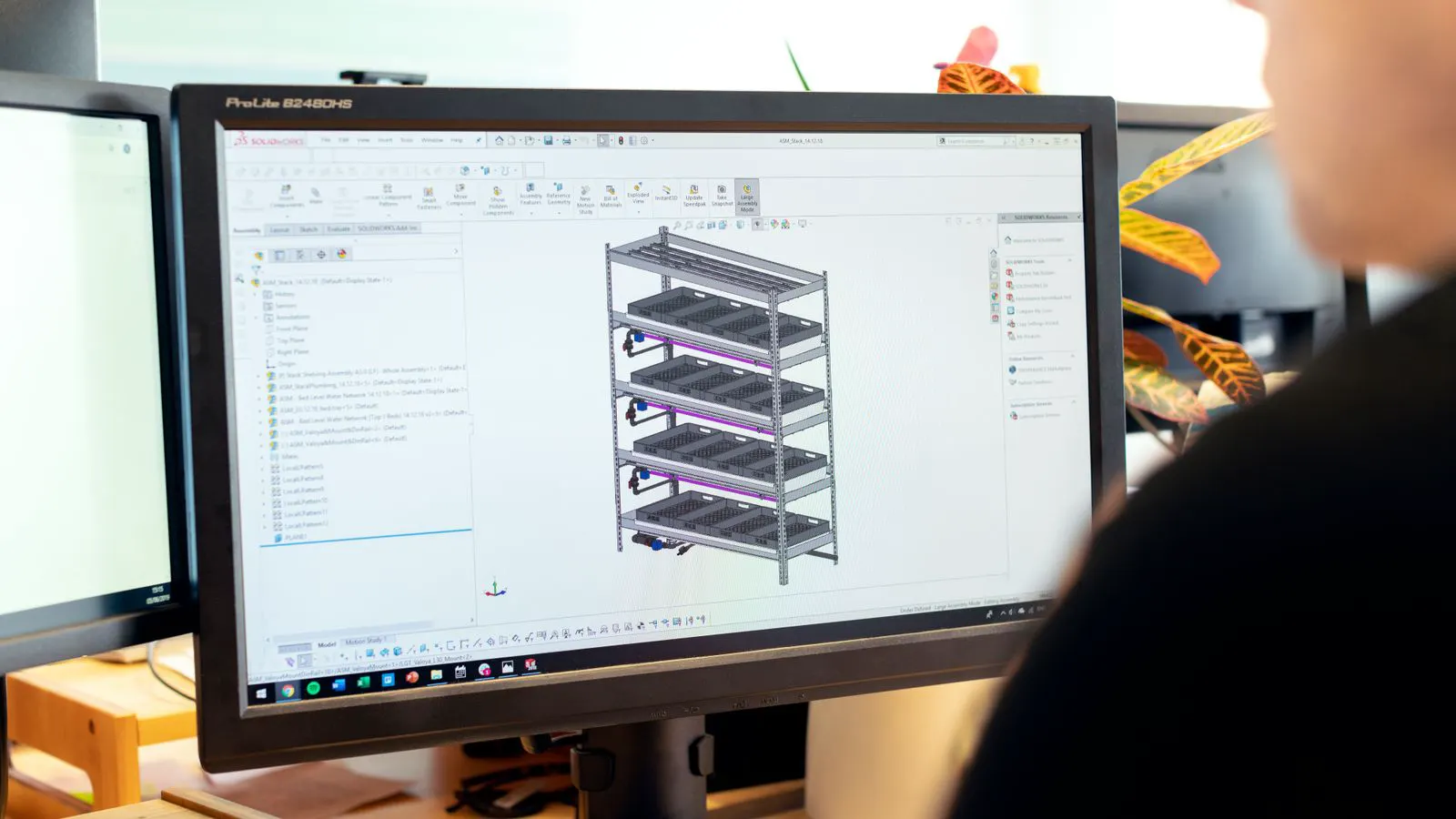
DfAM software helps engineers design parts that print reliably in metal and polymer. This guide explains how to evaluate options based on geometry control, simulation, material data, and workflow integration to choose the right additive design tools.
- DfAM software focuses on geometry control and printability, not just CAD modeling.
- Evaluate tools for their ability to handle supports, lattice structures, and topology optimization.
- Check integration with your existing CAD, CAE, and slicer or printer software.
- Material data and process constraints must be built into the design tool.
- Start with a pilot project to test workflow before committing to a license.
What Makes DfAM Software Different From Standard CAD
Standard CAD software was built for subtractive manufacturing. It assumes material is removed from a solid block. DfAM software flips that assumption. It treats the final part as a collection of layers and supports. Engineers must think about how the part will be built, not just how it will look.
The core difference lies in geometry control. A standard CAD model may have overhangs that are impossible to print without massive support structures. DfAM software helps identify and fix those issues early. It also encourages design patterns that reduce material waste and post-processing time.
Consider a complex bracket. In a standard CAD environment, you might model it as a solid block with holes and pockets. The tool checks for dimensional accuracy and interference with other parts. It does not care if a 40-degree overhang will require support material. In DfAM software, that same model is analyzed layer by layer. The tool flags the overhang, estimates the support volume, and suggests reorienting the part to reduce the support footprint. This shift in perspective changes how parts are designed.
This distinction matters because design errors discovered during printing are expensive. You lose build time, material, and machine hours. If you catch a warping issue in the software, the cost is a few minutes of modeling. If you catch it in the post-processing lab, the cost is a scrapped part and a delayed delivery.
Key Features to Evaluate in Additive Design Tools
When you review DfAM software, you need to look beyond the marketing copy. The tool must handle the specific challenges of additive manufacturing. Here are the primary features to test.
Geometry analysis is the first requirement. The software should flag overhangs, thin walls, and internal cavities that trap support material. It should suggest fixes, such as tilting the part or changing the orientation. For example, a thin horizontal flange might be stable in a solid model, but in a layer-based process, it may collapse or detach without support. Good DfAM software identifies these thin features and suggests increasing the wall thickness or reorienting the part so the flange becomes a vertical feature.
Topology optimization is another major feature. This algorithm removes material from a part without weakening it. It creates organic shapes that traditional CAD tools cannot produce. For metal parts, this can reduce weight by a significant margin. For polymer prototypes, it speeds up the build time. Imagine designing a support arm for a machine. Instead of a solid rod, topology optimization might create a web-like structure that transfers load along the strongest paths. The result is a lighter part that uses less material and prints faster.
Lattice generation is critical for specific applications. Engineers use lattices to create internal structures that are lightweight and strong. The software must allow you to control the density and pattern of the lattice. You need to ensure the lattice pattern is printable with your specific machine. A gyroid lattice might work well for a metal part, but the same pattern might not print cleanly in a polymer using a different process. The software should let you adjust the lattice parameters and preview how the structure will appear in the final build.
Simulation and process planning are also part of the workflow. The tool should help you understand how heat flows during the build. It should warn about potential warping or cracking. For metal printing, this is where you avoid expensive build failures. During a build, the part cools rapidly after each layer. This cooling creates thermal stress. If the stress exceeds the material’s yield strength, the part can crack or detach from the build plate. Simulation tools model this heat flow and stress distribution, allowing engineers to predict and mitigate these issues before the build starts.
How to Match Software to Your Manufacturing Process
There is no single best DfAM software. The right choice depends on your material, machine, and part type. Metal DfAM and polymer DfAM have different needs.
Metal printing requires tighter tolerances and stronger simulation. You need to understand heat transfer and thermal stress. The software should integrate with your powder bed fusion or electron beam melting workflow. It should also handle complex geometries that require precise support placement. In metal printing, the build plate and the part are heated together. As the part cools, it contracts. If the contraction is uneven, the part can warp. The software must account for this by adjusting support structures and build parameters to keep the part stable on the plate.
Polymer printing is more forgiving but still requires careful design. You need to manage shrinkage and warping. The software should help you orient the part to minimize these issues. It should also allow for easy slicing and layer height adjustment. In polymer printing, the material shrinks as it cools. This shrinkage can cause parts to curl or detach from the build surface. The software should suggest orientations that keep the part flat and reduce the risk of curling.
Consider the scale of your operation. If you are printing small prototypes, a lightweight tool may be enough. If you are producing production parts, you need a robust system that integrates with your quality control processes. For production, the software must handle large volumes of parts and ensure consistency. It should allow for batch processing and automated quality checks. For prototyping, the focus is on speed and flexibility. A tool that allows rapid design changes and quick prints is often more valuable than one with advanced simulation features.
Workflow Integration and Interoperability
A DfAM tool that does not fit your existing workflow will create friction. Engineers hate switching between multiple systems. They want a smooth handoff from design to print.
Check the file formats. Can the software export to STP, STEP, or 3MF? Can it import files from your main CAD system? If the tool cannot communicate with your existing setup, you will waste time converting files. For example, if your team uses a specific CAD package, the DfAM tool should be able to import models directly without losing geometry data. If you have to convert files, you risk losing details or introducing errors.
Look for API access. If you have a large team or multiple sites, an API allows you to automate data transfer. It reduces manual errors and speeds up the process. For instance, you could use an API to automatically send a new part design to the slicer and then to the printer. This automation reduces the time between design and print, and it minimizes the risk of human error in file handling.
Also consider the slicer. Some DfAM tools include a slicer. Others connect to a separate one. You need to know which one works best with your machine. If the slicer is poor, the design software is useless. The slicer determines how the 3D model is broken down into layers and how the material is laid down. A good slicer ensures that the part is printed as designed. If the slicer is not compatible with your machine, you will spend time troubleshooting print settings instead of designing parts.
Cost and Licensing Models
DfAM software is not cheap. You need to budget for licenses, training, and support. Licensing models vary by vendor. Some use per-seat pricing. Some use tiered pricing based on the features you use.
Look for a trial period. This is your chance to test the software with real parts. Do not rely on a demo. Use a part that you have already printed or designed. See how the tool handles your specific geometry. For example, if you have a part with complex internal channels, test how the software handles those channels. Does it suggest support structures? Does it warn about potential blockages? The trial period is your opportunity to see if the software fits your specific needs.
Training is often overlooked. If your engineers do not know how to use the tool, they will not use it. Ask the vendor for training materials, webinars, or on-site sessions. A good vendor invests in their customers. Training should cover not just the software interface, but also the underlying principles of DfAM. Engineers need to understand why certain design changes are necessary and how to interpret the simulation results.
Practical Evaluation Checklist
Use this checklist to evaluate DfAM software options. Print it out and use it during your demos.
- Does the tool handle overhangs and thin walls effectively?
- Can it generate topology optimized geometries?
- Does it support lattice structures for your specific material?
- Does it integrate with your existing CAD and slicer?
- Is there a simulation module for thermal stress?
- What is the file export format and compatibility?
- Is there an API for automation?
- What is the licensing cost and training support?
- Can you test it with a real part?
- How is the customer support structured?
Common Mistakes in Choosing DfAM Software
Many engineers make the same errors when buying DfAM software. They buy based on the logo. They buy based on the price. They buy based on the demo.
The biggest mistake is ignoring the material data. The software must know the properties of the material you use. If it does not, the simulation is useless. You need to ensure the tool has a library of materials that matches your shop. For example, if you are printing aluminum, the software must have accurate data on the thermal expansion and yield strength of that specific aluminum alloy. If the data is missing or incorrect, the simulation will give you false confidence. You might think a part is safe to print, but it could fail in the build.
Another mistake is underestimating the learning curve. DfAM software is different from standard CAD. It requires a new way of thinking. If your team is new to additive manufacturing, you need a tool with a gentle learning curve. A tool with a steep learning curve can delay the adoption of DfAM. Your engineers will spend time learning the software instead of designing parts. A good tool should have clear documentation and intuitive interfaces to help engineers get up to speed quickly.
Finally, do not skip the post-processing workflow. The software should help you plan support removal and finishing. If it does not, you will spend extra time in the lab. For example, if the software does not show where the support material will be, you will have to guess where to cut and grind. This guesswork can lead to damage to the part or unnecessary work in the lab. A good DfAM tool should provide clear visualizations of the support structures and suggest the best ways to remove them.
Final Decision Checklist
Before you sign the contract, run through this final decision checklist.
- Does the software solve your specific design problems?
- Is the workflow integrated with your existing tools?
- Does it support your materials and machines?
- Is the training and support adequate?
- Have you tested it with real parts?
- Does the cost fit your budget?
If you can answer yes to all of these, you are ready to buy. If not, keep looking. The right DfAM software will save you time and money in the long run.
Frequently asked questions
What is the difference between DfAM software and a slicer?
DfAM software focuses on design and geometry control. It helps you create parts that print well. A slicer prepares the model for the printer by defining layers and supports.
Do I need DfAM software if I use a standard CAD tool?
Standard CAD tools can be used for additive manufacturing, but they lack specific features for printability. DfAM software adds checks for overhangs, supports, and material constraints.
Is DfAM software only for metal printing?
No. DfAM software is used for both metal and polymer printing. The features and workflows differ based on the material and process.
How long does it take to learn DfAM software?
Learning time depends on your experience with CAD and additive manufacturing. New users may need a few weeks. Experienced engineers may adapt in a few days.
Can DfAM software replace my existing CAD system?
No. DfAM software works alongside your CAD system. It adds a layer of design analysis and optimization for additive manufacturing.