DfAM Checklist: Pre-Print Review for Metal
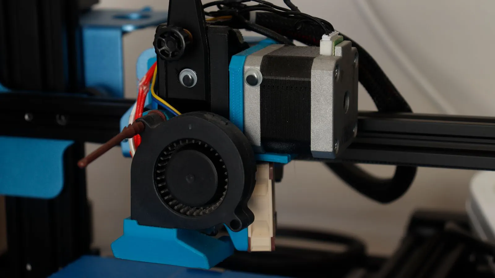
Use this metal print review checklist to verify part geometry before printing. It covers minimum wall thickness, support strategy, thermal management, and file integrity to prevent failed builds and reduce post-processing costs.
- Check minimum wall thickness against your specific powder bed or wire feed parameters.
- Plan support geometry before finalizing the CAD model.
- Verify heat flow paths and thermal mass distribution.
- Validate the STL or STEP file before release to the printer.
- Document exceptions to standard design rules for traceability.
1. Verify Minimum Wall and Feature Dimensions
The first line of defense in any metal print review is the geometry itself. Metal powders and molten metal behave differently than thermoplastics. The minimum wall thickness for a successful build depends on the specific process and machine parameters. For powder bed fusion systems, thin walls often fail because the powder bed cannot support the feature or the energy density cannot melt the material in a single scan. For wire feed processes, the minimum feature size is governed by the nozzle diameter and the machine’s speed.
A practical rule of thumb is to measure your thinnest walls and compare them to the machine’s verified minimums. Do not guess. If you are working with a new machine or a new material, request the process window from the machine operator or the material supplier. This window defines the range of scan parameters that produce a dense, defect-free part.
Red flags to watch for:
- Walls thinner than 0.8 mm in powder bed fusion processes, unless the machine has a specific thin wall mode.
- Features that are too close to each other, such as ribs or fins with gaps less than 1 mm.
- Thin, long features that are prone to deflection or thermal cracking.
If a wall is too thin, consider increasing the thickness, changing the orientation, or splitting the feature into two separate components. Sometimes the best fix is to remove the feature entirely. Ask if the feature is structurally necessary or if it was added for manufacturing convenience in a different process.
2. Assess Support Strategy and Removal
Supports are a major cost and time factor in metal additive manufacturing. They are not just a technical necessity; they are a design decision. A part that requires complex, inaccessible supports will take longer to print, cost more in powder or wire, and take longer to remove and inspect.
Before releasing a part for print, review the support structure generated by your slicing software. Look for supports that land on flat, accessible surfaces. Avoid supports that land on curved surfaces or in deep cavities. If supports are required on a curved surface, consider adding a small sacrificial block or a support base to the model. This adds material but makes removal much easier.
Check the attachment points. Supports should be attached to areas that can be ground or machined away without damaging the part’s functional surfaces. If a support attaches to a critical surface, such as a machined bore or a bearing seat, you will need to machine it back, which increases cost and reduces material efficiency.
Red flags to watch for:
- Supports that touch functional surfaces.
- Supports that are difficult to access with hand tools.
- High volumes of support material relative to the part volume.
A good target is to keep support volume below 15 percent of the part volume for most structural components. If the support volume is higher, re-evaluate the orientation or the geometry. Sometimes a 10 degree change in part orientation can reduce support volume significantly.
3. Manage Thermal Mass and Heat Flow
Metal parts are rigid and conduct heat well. This creates a problem for the printer. As the part cools, it contracts. If the part is large and thin, it can crack or warp as it cools. The key to managing this is to control the heat flow path.
Design your part to have a consistent thickness. Avoid sudden transitions from thick to thin sections. A thick section acts as a heat sink, cooling the adjacent thin section too quickly. This thermal shock can cause cracking. If you must have a thick section next to a thin one, add a ramp or a transition zone to equalize the thickness.
Consider the part’s orientation on the build plate. The bottom of the part is in contact with the hot build plate. The top of the part is exposed to the cooler chamber. This creates a temperature gradient. Design the part so that the most critical features are on the bottom or in the center of the build. Avoid placing critical features on the top edge, where they are most exposed to thermal stress.
Red flags to watch for:
- Sudden changes in wall thickness.
- Thin features attached to thick blocks.
- Critical features located on the top edge of the part.
If your part has a complex geometry, consider adding a sacrificial base or a support block. This adds material but provides a stable heat sink. It also helps prevent warping by keeping the part anchored to the build plate.
4. Check for Internal Geometry and Porosity
Internal geometry is a major risk factor in metal 3D printing. Hollow features, internal cavities, and enclosed voids are difficult to fill with powder. If powder remains trapped inside a hollow feature, it will not melt. This creates a void or porosity pocket. When the part is subjected to load, this void can act as a stress riser and cause failure.
For powder bed fusion, any enclosed cavity will likely contain unmelted powder. This is a defect. You must either remove the cavity or design it to be open. If the cavity is necessary for weight reduction, use a lattice structure or a topology optimization tool to create a pattern that allows powder flow. Avoid solid blocks of material with internal voids.
For wire feed processes, internal geometry is less of a concern because the wire is melted and deposited layer by layer. However, overhangs and deep cavities can still be problematic. The wire may not reach the bottom of a deep cavity, leaving a gap.
Red flags to watch for:
- Enclosed hollow features.
- Deep cavities with narrow inlets.
- Internal channels that are too small to fill.
If you must have an internal feature, make sure it is open to the exterior. Add a small drain hole or a vent. This allows powder to flow out and ensures the feature is filled with molten metal.
5. Review Surface Finish and Tolerances
Metal 3D printed parts have a specific surface finish. It is not smooth like a machined part. It has a “sandpaper” texture from the layer lines and the powder. This surface finish is acceptable for many applications, but it is not suitable for all.
If your part requires a smooth surface, plan for post-processing. Polishing, grinding, or machining will be required. This increases cost and time. Design the part to minimize the amount of surface that needs finishing. If a surface must be machined, leave a small amount of stock. This allows the machinist to remove the layer lines and achieve a smooth finish.
Tolerances are also different from traditional manufacturing. Metal 3D printing has a specific tolerance range. It is not as tight as CNC machining. If your part has tight tolerances, design it to be machined. Do not rely on the 3D printer to hold tight tolerances.
Red flags to watch for:
- Critical surfaces that require a smooth finish.
- Tight tolerances on features that are not machined.
- Surfaces that are difficult to access for post-processing.
If your part has a mix of critical and non-critical surfaces, mark the critical surfaces in the CAD model. This helps the post-processing team know where to focus their effort. It also helps with quality inspection.
6. Validate the File and Metadata
The last step in the pre-print review is to validate the file. A good part design can still fail if the file is corrupt or has the wrong units. Before sending the file to the printer, check the file type and the units.
For metal printing, STL and STEP files are commonly used. STL files are mesh files. They define the surface of the part. STEP files are solid files. They define the volume of the part. For metal printing, STEP files are preferred because they are easier to slice and have better accuracy. STL files can have gaps or holes that cause slicing errors.
Check the units. Make sure the file is in millimeters. If the file is in inches, the part will be 25 times too small. This is a common mistake. Always verify the units before slicing.
Check the file for errors. Use a mesh repair tool to check for non-manifold edges, inverted normals, and holes. A file with these errors will not slice correctly. It will produce a part with missing material or incorrect geometry.
Red flags to watch for:
- Wrong units in the file.
- Corrupt or damaged file.
- Non-manifold geometry.
Keep a record of the file version. If you make changes to the part design, save a new version. Do not overwrite the old file. This helps with traceability. If a part fails in service, you need to know exactly which version of the design was printed.
7. Document Exceptions and Approve
Not every part can be designed to fit perfectly within standard rules. Sometimes, business needs or customer requirements force you to break the rules. That is acceptable, but you must document it.
Create a DfAM exception log. List the features that do not meet the standard design rules. Explain why they are necessary. Get approval from the process engineer or the quality manager. This creates a paper trail. It also helps future designers learn from the experience.
For example, if you have a thin wall that is below the minimum thickness, document it. Explain why it is necessary. State the risk. Get approval to print it. If the part fails, you have a record of the decision. If the part succeeds, you have learned what the machine can handle.
This documentation is part of the metal print review process. It is not just about checking the geometry. It is about managing risk and maintaining quality.
A complete pre-print review should take 15 to 30 minutes for a simple part and up to an hour for a complex part. It is not worth skipping. A small error in the design can cause a failed build. A failed build wastes powder, time, and money. It also delays the project.
The 3D printing design rules are not laws. They are guidelines based on experience. But they are there for a reason. Follow them, and you will have a higher success rate. Break them, and you must be prepared to manage the consequences.
Use this checklist for every part. It will save you time and money. It will also improve the quality of your parts. It is the difference between a professional operation and a risky experiment.
Start with the geometry. Check the supports. Manage the heat. Review the internal features. Check the surface finish. Validate the file. Document the exceptions. That is the metal print review.
Do it before you print. Do it every time. Do it well.
Frequently asked questions
What is the minimum wall thickness for metal 3D printing?
It depends on the machine and the material. For most powder bed fusion systems, walls thinner than 0.8 mm are at risk. For wire feed processes, the minimum is often larger. Always check the machine's process window.
Can I print a part with enclosed hollow features?
No. Enclosed hollow features will trap powder and create voids. You must make the feature open or use a lattice structure that allows powder flow.
How do I reduce support material?
Change the part orientation. Design flat surfaces to sit on the build plate. Avoid overhangs. Add support blocks to make removal easier. Keep support volume below 15 percent of the part volume.
What file format should I use for metal printing?
STEP is preferred for metal printing. It is a solid file with better accuracy. STL is a mesh file that can have gaps and holes. Use STEP for complex parts.
Do I need to leave stock for machining?
Yes. If a surface must be machined, leave a small amount of stock. This allows the machinist to remove the layer lines and achieve a smooth finish. Do not rely on the 3D printer to hold tight tolerances.