DFAM Software Trends for Industrial Design Teams
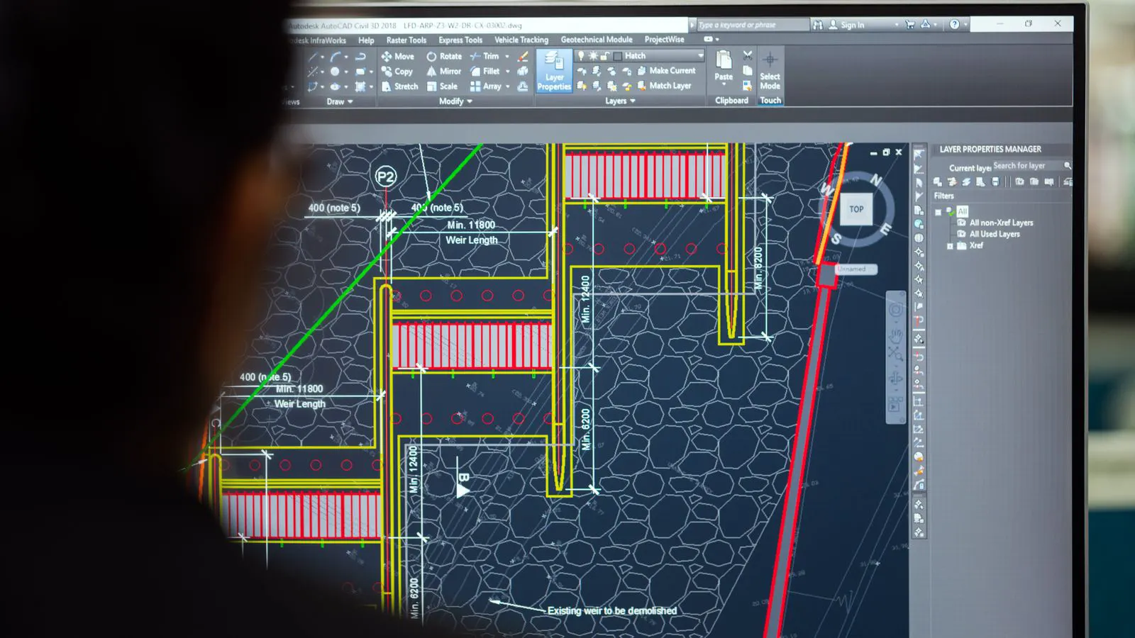
DFAM software is moving beyond basic CAD toward integrated, data-driven workflows. Teams should plan for tighter simulation feedback, automated part validation, and cloud-based generative tools. These shifts demand early software evaluation and structured team training to avoid costly rework.
- Design for Additive software is shifting from standalone CAD plugins to integrated, data-driven workflows.
- Generative design tools now handle complex topology optimization for metal AM parts.
- Simulation and post-processing software are moving upstream to predict defects before printing.
- Teams should pilot DFAM software with real parts, not just digital concepts.
- Standardizing file formats and data pipelines reduces handoff friction between design and production.
Why DFAM Software Is Moving Beyond CAD
Design for Additive software no longer starts and ends at the CAD model. Industrial teams now expect the design environment to talk to simulation, material databases, and printer controllers. The old workflow, where an engineer exported a STEP file and a production team manually checked it for support feasibility, is breaking down.
The shift is practical. A pump housing designed for metal powder bed fusion must account for heat flow in the build plate. A lattice structure for a drone frame needs to match the machine’s minimum feature size. If the software cannot check those constraints in real time, the part fails in production or requires costly redesigns.
Buyers evaluating additive design software should look for tools that close the gap between design intent and machine capability. The best platforms today act as a bridge, not just a drawing tool. Consider a titanium valve body. In a traditional CAD workflow, a designer models the internal flow channels and checks for manufacturability using basic rules of thumb. In a modern DFAM environment, the software validates the geometry against the specific laser power and scan strategy of the selected 3D printer. It flags narrow corners that cannot be filled by the powder bed and ensures that the part’s thermal mass does not exceed the cooling capacity of the build chamber.
This integration reduces the cognitive load on the engineering team. Instead of switching between a CAD viewer, a simulation solver, and a slicer interface, the engineer works in a single environment. The software knows that a 0.4 mm feature size might be feasible on a specific high-resolution machine but impossible on a standard production unit. This context-awareness prevents the costly discovery of a manufacturing error after the part has already been released for build preparation.
How Generative Design Changes Part Topology
Generative design software takes a set of functional requirements and produces multiple structural solutions. For metal AM, this means the software can remove material from a bracket, a valve, or a turbine blade to meet weight, stiffness, and load targets.
The output is not a smooth, machined shape. It is a topology-optimized structure with internal channels, organic curves, and varying wall thicknesses. Traditional design tools handle this geometry poorly. They struggle with complex Boolean operations and organic surfaces.
Teams using generative design for AM need to adjust their review process. A part that looks unusual in a CAD file may be perfectly valid if it meets the simulation criteria. The challenge is training designers to trust the algorithm while still applying engineering judgment.
A common mistake is treating the generated model as final. Teams should export the topology, run a finite element analysis, and check for stress concentrations at support interfaces. The software generates the shape; the engineer validates the physics.
Consider a motor mount for an electric vehicle. A traditional machined design uses a solid aluminum block with drilled holes. A generative design approach might produce a skeletal structure with curved, flowing geometry that distributes vibration loads across the entire surface area. The result is significantly lighter. However, the organic curves create challenges for support placement. The software must calculate where supports are needed without adding too much material that must be removed later. The engineer must then verify that the support contact areas do not cause surface defects that affect the part’s function.
Another key aspect is the definition of constraints. If the software does not know the exact mounting points, the load vectors, and the allowable deflection, the output will be generic. Engineers must define the boundary conditions explicitly. This includes the direction of forces, the temperature range the part will operate in, and the maximum allowable stress. The more precise the input, the more useful the output. The software is a tool for optimization, not a substitute for engineering intent.
What Simulation Software Adds to the DFAM Workflow
Simulation software predicts how a part behaves during and after printing. For metal AM, this includes thermal stress, residual stress, and distortion. For polymer AM, it covers shrinkage, warping, and support removal damage.
The value is in catching problems early. A long, thin cantilever in a nylon part will warp if the support strategy is wrong. A thick, uneven wall in a titanium bracket will crack during cooling. If the software checks this before the build starts, the team avoids a failed print and a scrap part.
Buyers should evaluate simulation tools based on their integration depth. A standalone solver that requires manual meshing and material input adds friction. A tool that pulls material properties from the printer’s database and applies them automatically reduces setup time.
The trend is moving toward real-time or near-real-time feedback. Designers can see predicted distortion while they model. They adjust wall thickness or add ribs immediately. This closes the loop between design and production faster.
Simulation is particularly critical for parts that undergo post-processing. A 3D printed part is often machined to achieve final tolerances. If the simulation predicts that the part will distort by 0.5 mm during cooling, the engineer can adjust the design geometry before slicing. This ensures that the final machined part meets the required dimensions. Without this step, the production team might machine the part based on the CAD model, only to find that the actual part is out of tolerance due to print distortion.
For polymer parts, simulation helps predict warping caused by anisotropy. Fused Deposition Modeling (FDM) parts are stronger in the Z-axis but weaker in the XY-plane. Simulation can show how a thin wall might crack if the part is subjected to bending loads. By orienting the part differently on the build plate, the engineer can align the part’s structural axes with the machine’s strongest axes. This simple adjustment, guided by simulation, can prevent part failure in the field.
How Workflow Automation Reduces Handoff Errors
DFAM workflow automation connects design, simulation, and production data. When a part passes simulation, the software automatically generates support structures, slice parameters, and machine files. The production team receives a build-ready package, not a raw CAD file.
This reduces errors at the handoff point. A designer might export a file with the wrong material grade. A production engineer might slice it with incorrect layer orientation. Automation removes these manual steps.
The key feature to look for is a unified data pipeline. The part design, simulation results, and machine parameters should live in one system. If the simulation fails, the software flags the part and sends it back to the designer with the error code. The production team never sees a failed part.
Teams using automated workflows report fewer rework cycles. The software acts as a gatekeeper, checking every part against the same set of rules. This consistency matters in high-volume production where one bad build can halt a line.
Automation also improves traceability. Every part build is linked to a specific version of the design file, a specific set of simulation results, and a specific machine configuration. If a batch of parts fails in the field, the team can quickly identify which software version and machine settings were used for that batch. This is essential for quality control and regulatory compliance in industries like aerospace and medical devices.
Without automation, data is fragmented. Design files sit on one server, simulation results on another, and machine files on the production floor. This fragmentation creates opportunities for error and makes it difficult to replicate successful builds. A unified pipeline ensures that the “recipe” for the part is preserved and consistent.
What Buyers Should Do Now
The software market is moving fast. Teams that wait for the perfect tool will face production delays. The best approach is to pilot with a real part, not a digital concept. Pick a part that has already failed in production or required multiple redesigns. Run it through a new DFAM platform and measure the time saved.
Start with the metal or polymer process you use most. If your team prints metal parts for pump housings, focus on tools that handle metal AM topology and thermal simulation. Do not buy a platform that promises everything but excels at nothing.
Standardize your file formats. Many teams still rely on STEP for design and X3D or proprietary formats for slicing. This creates friction. Pick one neutral format for handoff and build your workflow around it.
Train your team on the new tools, but do not rely on them to replace engineering judgment. Generative design produces many options. Simulation predicts outcomes. The engineer decides which option meets the functional requirements. The software assists; it does not replace.
When selecting a pilot part, choose one with known failure modes. A part that previously cracked during cooling or distorted during support removal is ideal. By running this part through the new software, the team can directly compare the predicted outcomes with the historical data. If the simulation accurately predicted the previous failure, confidence in the tool will grow. If the software suggests a design change that prevents the known failure, the value proposition becomes clear.
Also, evaluate the software’s ability to handle your specific materials. Not all DFAM platforms have complete material databases for every process. If your team prints with a specific alloy or polymer, ensure that the software has the correct thermal and mechanical properties for that material. Missing or inaccurate material data will lead to unreliable simulation results.
Table: Key DFAM Software Features to Evaluate
| Feature | What to Look For | Common Mistake |
|---|---|---|
| Topology Optimization | Handles complex load cases and boundary conditions | Assuming the generated shape is print-ready without simulation |
| Thermal Simulation | Accounts for build plate orientation and cooling rates | Running static FEA without dynamic thermal analysis |
| Support Generation | Adapts to part geometry and printer capability | Using default support settings for all parts |
| Data Pipeline | Connects CAD, simulation, and slicing in one environment | Manual file exports between design and production |
| Material Database | Links material properties to printer and process parameters | Entering material data manually for each build |
How to Prepare Your Team for DFAM Software
The human side of the transition matters as much as the tooling. Designers need to learn how to write clear functional requirements for generative design. If the inputs are vague, the outputs are useless. A requirement like “make it lighter” produces weak results. A requirement like “reduce mass by 30 percent while maintaining 500 N load at the mounting points” produces a usable structure.
Production engineers need to understand the data the software generates. They should be able to read a simulation report, identify a stress concentration, and decide whether to adjust the design or the print parameters.
Start with a small pilot group. Pick two or three engineers who are comfortable with new tools. Give them a defined project scope. Do not ask them to redesign your entire product line. Let them solve one part problem well. Document the process. Then scale.
The goal is not to replace traditional design skills. It is to extend them. A strong DFAM team uses CAD, simulation, and automation together. The software handles the repetitive checks. The engineer handles the engineering.
Training should focus on the workflow, not just the software interface. Engineers need to understand how the software thinks. For example, they should know why the topology optimizer removes material in certain areas and how the support algorithm determines where to place supports. Understanding the logic behind the software allows engineers to troubleshoot issues and interpret results correctly.
It is also important to establish clear roles and responsibilities. Who is responsible for defining the constraints? Who reviews the simulation results? Who approves the final design for build? Without clear ownership, the workflow can become chaotic. The software can generate hundreds of options quickly, but only a human can make the final decision based on business and engineering factors.
Final Thoughts
DFAM software is becoming a core part of industrial design. The tools that will define the next decade are those that integrate design, simulation, and production data. Teams that invest in these platforms early will reduce rework, shorten lead times, and improve part quality.
The market is not static. New features appear regularly. The best strategy is to evaluate tools based on your specific process needs, not on marketing claims. Run pilots, measure results, and scale what works.
The shift is already happening. The question is whether your team is ready to adopt it.
Frequently asked questions
What is the biggest gap between current CAD and DFAM software?
Current CAD tools often lack real-time checks for printability. They do not automatically verify support feasibility, thermal stress, or machine constraints during the design phase.
How does generative design differ from traditional topology optimization?
Generative design uses algorithms to explore many structural solutions based on functional inputs. Traditional topology optimization often starts with a solid block and removes material based on a single load case.
Do I need to replace my existing CAD software?
No. Most teams integrate DFAM plugins or companion tools into their existing CAD environment. The goal is to add checks and automation, not to change the entire design workflow overnight.
What is a good first step for a team new to DFAM software?
Pick one part that has a known production issue. Run it through a DFAM platform to see where the software adds value. Measure the time saved and the quality improvements before expanding.
How important is material database integration?
It is critical. Material properties drive simulation accuracy. If the software does not link material data to printer parameters, teams must enter values manually, which introduces errors and slows down the workflow.