Outlook: Additive Design Software in 2026
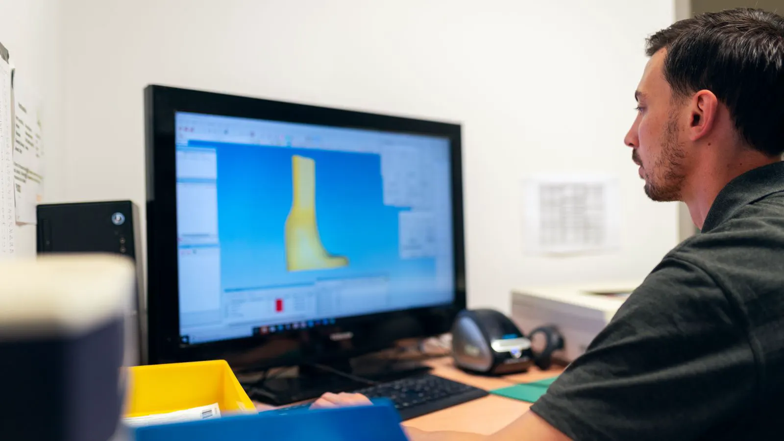
Additive design software in 2026 is shifting toward integrated AI and automated DfAM checks. Buyers should plan for tools that handle topology optimization, build orientation, and support generation within a single environment to reduce manual rework and improve part reliability.
- Design tools are merging AI generation with traditional CAD to reduce manual modeling time for complex topologies.
- Automated support and orientation analysis is moving from post-processing to a core part of the design phase.
- Buyers should evaluate software based on data continuity, material knowledge integration, and workflow integration.
- Standard workflows will require tools that bridge design intent and production parameters without manual re-entry.
From Manual Modeling to Guided Generation
Industrial design teams are moving away from purely manual CAD modeling when producing parts for additive manufacturing. The core challenge is no longer just drawing a shape. It is deciding how that shape will survive the printing process. Additive design software is evolving to handle this decision early in the workflow. Teams now expect tools to suggest geometry, predict failure points, and calculate material usage before a single layer is printed.
Consider a structural bracket for a medical device. A traditional engineer might start with a solid block and subtract material based on stress analysis. An additive design workflow starts by defining the load paths and the material limits. The software then proposes a topology that uses less mass while maintaining stiffness. The resulting part has organic-looking lattice structures and curved ribs that look strange in a standard CAD environment but perform well under load. This shift changes the engineering conversation from “how do I model this part?” to “what are the constraints, and how do I validate the result?”
This shift changes how engineering teams allocate time. Instead of spending weeks on iterative manual revisions, engineers focus on defining constraints and validating AI-generated options. The software acts as a decision support system. It evaluates thousands of topology variations against load, weight, and manufacturability criteria. This approach reduces the risk of parts that look good on screen but fail during post-processing or in service. The engineer’s role becomes one of curation and verification rather than pure geometric construction.
What Will Define Standard DfAM Workflows
The definition of a standard workflow is changing. Five to six shifts are already visible across major design environments. These shifts will define which tools become the default for professional buyers over the next few years.
- Integrated topology optimization and generative design.
- Automated support structure prediction and evaluation.
- Material-specific design rules embedded in the software.
- Real-time build orientation analysis during modeling.
- Direct data handoff to slicing and machine control.
Buyers should treat these capabilities as baseline expectations. A tool that only models geometry without considering the additive process creates friction. It forces engineers to guess at support needs and orientation impacts. The standard is moving toward a single source of truth where design and production parameters live together.
Take support structure generation as an example. In the past, an engineer would model a part, switch to a slicing program, and then manually add supports. If the part had a long overhang, the supports would be thick and difficult to remove, potentially damaging the part surface. Now, the design software analyzes the geometry and suggests support placement before the part is even sent to the slicer. It can even suggest modifying the geometry slightly to eliminate a difficult overhang, saving material and post-processing time. This integration is no longer a “nice to have” feature. It is a fundamental requirement for efficient production.
How AI Tools Are Changing Design Speed
AI design tools are no longer experimental features. They are becoming standard components of professional additive design software. These tools use machine learning to analyze past print data and simulate outcomes. They predict where thermal warping will occur and where overhangs will require support.
For a buyer, this means a different evaluation criterion. You no longer just look at the quality of the initial geometry. You look at the accuracy of the predictions. Does the software correctly identify the weak points in a titanium bracket? Does it flag a thin-walled resin part that is likely to delaminate? The value lies in the confidence of the simulation.
Imagine a team printing a large, complex housing in aluminum. A manual design might result in a part that warps during the print because the thermal mass is unevenly distributed. An AI-assisted tool can detect this imbalance and suggest adding local ribs or changing the build orientation to mitigate the stress. The engineer does not need to run a full finite element analysis to catch this. The software flags it as a potential issue during the design phase. This speed-up is significant. It allows for faster iteration cycles and reduces the cost of failed prototypes.
Generative design future trends show a move toward multi-objective optimization. Software can now balance weight, stiffness, and print time simultaneously. A single click can generate five or ten variations. The engineer selects the one that best fits the production schedule and material budget. This reduces the guesswork involved in selecting a build orientation. The tool also helps in minimizing build time by identifying the most efficient layer orientation for the specific machine. For a production line, this can mean the difference between a part that finishes in a night and one that takes three days to print.
The Role of Material Knowledge in Software
Additive design software is becoming more sophisticated in how it handles material data. Generic design rules are being replaced by material-specific knowledge bases. Each material behaves differently during the build. A nylon SLS part behaves very differently from a carbon fiber composite in FDM. The software must account for these differences.
Buyers should check if the software supports custom material profiles. Can you input the specific shrinkage rate of your resin? Can you define the powder flow rate for your metal powder? When the software has accurate material data, its DfAM recommendations become significantly more reliable. This is particularly important when moving from prototype to production. The part that works with a generic profile may fail with a specific industrial material.
For instance, consider a polymer part printed via Selective Laser Sintering. The software needs to know the thermal conductivity, the melting point, and the coefficient of thermal expansion. If these values are generic, the software might predict that a part will not warp. However, if you are using a specific high-performance nylon with a higher shrinkage rate, the part might warp significantly. Accurate material data allows the software to recommend a specific cooling rate or a support structure that compensates for the material’s behavior. This level of detail is what separates a tool that helps you design from a tool that just creates shapes.
Evaluating Tool Integration and Data Flow
A major friction point in many teams is data loss between design and production. If the design file is exported and then re-sliced, parameters are often lost or re-entered. This leads to errors. The software of 2026 must handle this data flow better.
The goal is a direct handoff. The design software should pass the build orientation, support strategy, and material settings directly to the slicer. This eliminates manual re-entry. It also reduces the chance of a mismatch between the intended design and the actual print parameters. For a B2B buyer, this integration is a key differentiator. It saves hours of manual setup and reduces the risk of production delays.
Think about the scenario where a part is designed in one system and printed on a different machine in another location. Without direct data flow, the operator at the printing site has to manually set the layer height, infill pattern, and support type. If they make a mistake, the part fails. With direct integration, the design software sends a file that contains all the necessary parameters. The slicer or machine control software reads this file and applies the settings automatically. This ensures consistency across multiple machines and multiple operators. It is a critical factor for quality control in a distributed manufacturing environment.
| Evaluation Criterion | Why It Matters for Buyers |
|---|---|
| Data continuity | Prevents parameter loss between design and slicing |
| Material database | Ensures DfAM recommendations match specific industrial materials |
| AI prediction accuracy | Reduces the need for physical trial and error |
| Workflow integration | Cuts setup time and manual re-entry errors |
| Scalability | Supports large teams with multiple concurrent projects |
How to Prepare Your Team for These Changes
Preparing for these shifts requires more than just buying new software. It requires changing how your team works. Engineers need training on how to interpret AI suggestions. They need to understand why the software recommends a specific topology. Blindly accepting generated geometry can lead to parts that are difficult to inspect or repair.
Start by mapping your current workflow. Identify where data is lost or where manual re-entry happens. These are the areas where new software will provide the most value. Also, review your material data. If your profiles are generic, the software will not give you reliable DfAM advice. Clean, specific material data is the foundation of good additive design.
Consider a team that has been using standard CAD for years. Their engineers are skilled in drawing and modeling but may not be familiar with the constraints of additive manufacturing. When they switch to a new DfAM software, they may be overwhelmed by the number of options and predictions. Training is essential to bridge this gap. Engineers need to learn how to read the simulation outputs and how to adjust the input parameters to get the desired result. They need to understand that the software is a partner, not a replacement for their judgment.
Finally, consider your team’s skills. You may need to hire or train engineers who understand both traditional CAD and additive manufacturing principles. The intersection of these skills is where the new tools deliver their value. A designer who understands how powder flows or how resin cures can use AI tools much more effectively. They can anticipate the issues that the software might flag and make informed decisions to resolve them. This cross-functional expertise is becoming increasingly valuable in the industry.
A Practical Checklist for Buyers
When evaluating additive design software, use this checklist. It focuses on practical capabilities rather than marketing claims.
- Can the software import your current CAD files without loss of data?
- Does it support the specific materials you use in production?
- Can it predict support needs before you generate them?
- Is there a direct export to your slicer or machine control software?
- How does the software handle updates to material or process parameters?
- Can you audit the AI decisions? Can you see why a specific topology was suggested?
If the software cannot answer these questions clearly, it may not be ready for your production environment. The goal is a tool that fits your workflow, not one that forces your team to change their habits.
Final Thoughts
The future of additive design software is clear. It is moving toward integration, automation, and material intelligence. Buyers who plan for these shifts will be in a strong position. They will reduce development time and improve part reliability. The tools are ready. The task is to select the right one for your specific needs.
Frequently asked questions
How do AI design tools reduce development time?
AI tools generate multiple geometry options quickly and predict failure points. This reduces the number of physical prototypes needed and cuts down on manual rework.
Can existing CAD files be used with additive design software?
Yes, most modern tools can import standard CAD formats. However, the software adds a layer of additive-specific analysis on top of the existing geometry.
What is the biggest mistake buyers make when evaluating these tools?
The biggest mistake is ignoring material data. Software with generic material profiles will give unreliable DfAM recommendations for specific industrial materials.
Do I need to retrain my whole team for new software?
You do not need to retrain everyone. You need to train your core engineers on how to interpret AI suggestions and manage the new workflow. The learning curve is manageable with proper guidance.
How do I know if my current software will be replaced?
Check if your current tool offers automated support prediction and direct data handoff to slicers. If it lacks these features, it is likely not aligned with current industrial workflows.