How to Machine 3D Printed Metal Parts
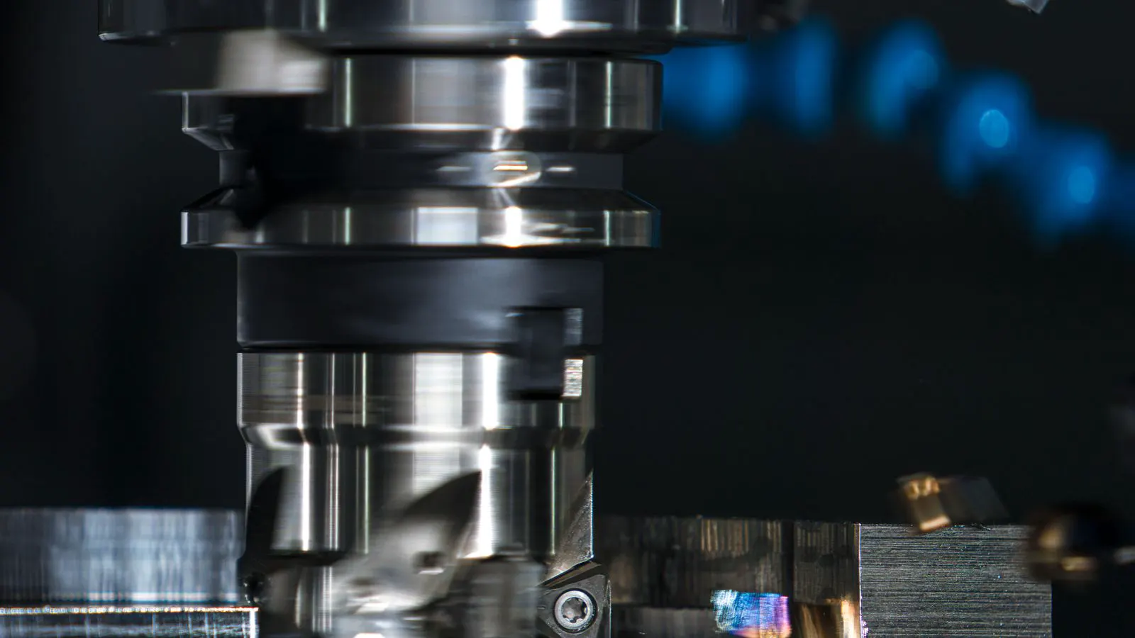
Machining 3D printed metal parts involves removing excess material to achieve precise final dimensions. This process typically uses CNC milling, turning, or grinding after support removal. Correct tooling, cooling, and measurement sequences ensure tight tolerances and surface quality for functional metal components.
- Machine only after full support removal and surface preparation to avoid tool damage
- Use sharp, rigid tools and controlled feeds to manage heat and tool wear
- Always verify dimensions with calibrated instruments before and after machining
- Account for residual stress and thermal distortion by machining in the correct sequence
- Document each cut to maintain traceability for quality and inspection
Why Machining Metal AM Parts
Metal additive manufacturing produces parts with near-net shape, but final dimensions rarely match production specifications. Surface texture from the powder bed, support material, and process distortion must be removed to meet functional requirements. Machining 3D printed metal parts converts a near-net-shape component into a precision part ready for assembly or service.
The goal is not simply to cut material away. It is to remove the minimum amount needed to reach tolerance while preserving material integrity. Every cut adds cost, cycle time, and potential for error. The process must be planned as carefully as the build itself.
What You Need Before You Start
Before the first tool touches the part, confirm that the part is ready for machining. This means full support removal, deburring, and a clean surface free of loose powder. Check the part for cracks, porosity, and dimensional drift after heat treatment. If the part failed inspection after heat treatment, machining will not fix the underlying defect.
Gather the following items and documents:
- Final drawing or CAD model with tolerance callouts
- Material certification for the alloy used
- Heat treatment record for the part
- Inspection report confirming absence of critical defects
- Fixturing plan showing how the part will be held in the machine
- Tooling list with holder numbers and insertion depths
- Cutting fluid or coolant specification
- Calibrated measurement instruments: micrometer, bore gauge, height gauge, CMM access if needed
Do not skip the fixturing plan. A part that shifts even slightly during cutting will throw out every subsequent feature. Design the fixture so the part is supported where it will be machined, not just where it sits on the table.
Step-by-Step Machining Process
1. Verify the As-Built Part
Place the part on a calibrated plate and measure the major dimensions. Record the as-built values in a document. This baseline tells you how much material exists between the current surface and the target tolerance. If a dimension is already inside tolerance, do not cut it. Cutting a part that is already in range wastes material and adds risk.
Reason: You cannot remove material that is not there. Knowing the starting point tells you the minimum cut per feature.
2. Select the Machining Strategy
Decide which features need machining and in what order. Typically, large flat faces are cut first to create a stable reference. Then step down to secondary features, then to small holes and critical diameters. Leave critical features for the final pass so they are not disturbed by subsequent operations.
Reason: Removing large volumes first creates a rigid base. Cutting small features first risks them being damaged by later cuts or fixture adjustments.
3. Fixture the Part
Hold the part with a dedicated fixture or vise. The contact points should be on non-critical surfaces and should not interfere with tool paths. Use clamping force that holds the part without deforming thin walls. If the part is small or thin, consider a soft jaw or a custom fixture block.
Reason: A part that moves during cutting will produce out-of-tolerance features and can break a tool. A secure fixture is the first line of defense against scrap.
4. Set Zero and Reference the Machine
Establish the work coordinate system. Use a calibrated probe or a precision edge finder to locate the part origin. Verify the Z0 position by probing the top surface. Confirm that the tool length offset is correct for each tool in the program.
Reason: An incorrect zero causes the tool to hit the table or miss the part entirely. A wrong tool length offset can crash the spindle.
5. Run a Dry Cycle
Load the program and run it at reduced speed with the tool retracted. Watch the tool paths for collisions, deep pockets, or areas where the fixture blocks access. Adjust the program if any tool path crosses a clamp or support pad.
Reason: A dry cycle catches programming errors before a physical tool contacts the part. It also confirms that the fixture and part alignment match the model.
6. Machine the Primary Surfaces
Cut the main flat faces and large bores. Use a conventional milling or turning strategy with appropriate feed and speed for the alloy. Keep the chip load consistent to avoid built-up edge or work hardening. Monitor coolant flow and tool condition after each pass.
Reason: Primary surfaces define the reference geometry for all other features. Cutting them first with the correct tooling establishes the part’s true dimensions.
7. Machine Secondary Features
Move to smaller features such as stepped bores, slots, and non-critical holes. Use smaller tools with shorter overhangs. Reduce feed rates where stiffness is lower. Check the surface finish after the rough pass before finishing.
Reason: Smaller tools are more flexible. Aggressive cutting on secondary features can bend the tool or cause vibration marks.
8. Finish Critical Features
Machine the final tolerance features. Use a light finishing pass with a sharp tool. Reduce feed to the minimum that maintains a continuous chip. Keep the tool engaged as long as possible to avoid chatter. Measure the feature immediately after cutting.
Reason: Critical features determine function. A finishing pass removes the tool marks left by roughing and locks in the final dimension.
9. Deburr and Clean
Remove all burrs from edges and holes. Use a small burr removal tool, a deburring tool, or a finishing stone. Clean the part with solvent or compressed air to remove metal chips and coolant residue.
Reason: Burrs catch in assemblies and create stress concentrations. Residue can hide surface defects during inspection.
Common Mistakes That Cause Scrap
| Mistake | Consequence | Prevention |
|---|---|---|
| Cutting a feature that is already in tolerance | Wasted material, added cycle time, risk of defect | Measure first. Only cut what is out of tolerance. |
| Fixturing on a critical surface | Part shifts, tolerance lost, surface damaged | Design fixture to contact non-critical areas. |
| Using a dull tool on a hard alloy | High tool wear, poor finish, work hardening | Inspect tools. Replace when wear is visible. |
| Ignoring residual stress | Part warps after cutting, final dimension out of tolerance | Machine in the correct sequence. Allow stress to settle between cuts. |
| Skipping the dry cycle | Tool collision, fixture damage, part scrap | Always run a reduced-speed simulation before cutting. |
Another frequent error is assuming that the part will behave like a machined billet. Metal AM parts carry different residual stresses and microstructural patterns. A tool path that works on a forged part may need different feeds and speeds on a printed part. Adjust based on material response, not habit.
Final Verification and Inspection
After all machining is complete, re-measure the part against the drawing. Use calibrated instruments for each feature type. Check critical dimensions first. Then inspect surface finish, hole location, and edge quality. Compare the measured values to the as-built record to confirm that the machining removed the correct amount of material.
If a feature is out of tolerance after final measurement, stop. Do not attempt a second finish pass unless the drawing allows it and the material condition supports it. Document the result. If the part fails, log the reason. If it passes, mark it as finished and release it to the next step.
Reason: The final check is the only moment when the part is judged as a finished product, not as a work in progress. Missing a defect here means shipping a bad part.
Practical Notes for Engineers
Plan the machining strategy from the start, not after the part is built. If a feature is critical, design the build orientation so that the feature is accessible to a tool without excessive overhang. This reduces tooling cost and improves finish.
Keep a record of every cut. Note tool number, feed, speed, and coolant. If a part later fails in the field, that record helps isolate whether the problem was process, material, or design.
Use the same measurement method for the as-built and final inspection. Switching from a CMM to a hand micrometer between checks can introduce error that is larger than the tolerance itself.
Machining 3D printed metal parts is not a secondary step. It is a controlled manufacturing operation that requires the same discipline as machining a traditional part. Treat it as such, and the process produces reliable results.
Frequently asked questions
Can I machine a metal AM part before support removal?
No. Support material can damage tools and ruin the surface. Remove all supports and deburr before cutting.
What tool should I use for a stainless steel AM part?
Use a sharp carbide tool with a short overhang. Keep feed low and coolant flow high to manage heat and built-up edge.
How much material should I leave for finishing?
Leave at least one to two millimeters above the target dimension on critical features. This allows a controlled finish pass.
Does residual stress affect machining accuracy?
Yes. Residual stress can cause the part to move after material is removed. Machine in the correct sequence and re-measure between operations.
How do I know if the part is ready for machining?
Confirm that supports are fully removed, the surface is clean, and inspection shows no critical defects. Verify the material and heat treatment records before starting.