Troubleshooting: Metal AM Surface Roughness
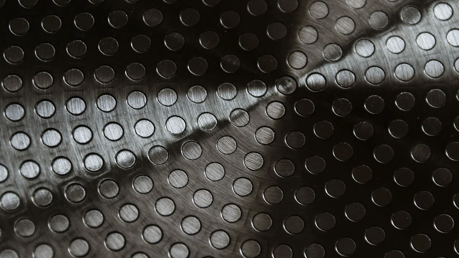
Metal AM surface roughness often stems from laser parameters, powder quality, or build orientation. This guide explains how to diagnose the symptom, identify the root cause, and apply targeted fixes to improve part surface quality before or after printing.
- Surface roughness in metal AM is usually a combination of process, powder, and part design issues, not a single failure.
- The primary causes include laser energy density, powder particle size, support design, and build orientation.
- Finishing methods range from abrasive media blasting and CNC milling to chemical polishing and laser texturing.
- Prevention requires consistent powder handling, calibrated machine parameters, and early design reviews for critical surfaces.
- Inspect parts at multiple magnifications to distinguish between process texture and actual defects.
Why Metal AM Parts Look Rough
Metal AM parts rarely come off the build plate with a factory-smooth finish. The surface shows layered lines, a matte texture, or even a granular appearance. This roughness is expected to some degree, but it becomes a problem when it affects fit, function, or aesthetics.
The texture comes from the deposition process itself. Each layer of molten metal solidifies on top of the previous one. The laser scans these layers in a specific pattern, and the transition between layers creates a stepped surface. Powder that does not fully melt also contributes to the roughness.
Engineers treat this surface condition as a post-processing input, not a defect to ignore. The goal is to understand what is driving the roughness and select the right finishing method. A part that needs tight tolerances will require a different approach than a decorative part or a component that will be machined.
Common Causes of Surface Roughness
The main drivers of rough metal AM parts are usually process settings, material quality, and design choices.
Laser and scan parameters. If the laser power is too low, the molten pool does not fully melt the powder. The result is a porous, rough surface. If the power is too high, the melt pool becomes unstable. This can create balling, porosity, or excessive spatter, all of which increase roughness. Scan speed and hatch spacing also matter. A slow scan speed with wide hatch spacing can leave unmelted powder between lines. A fast scan speed with tight spacing can over-melt the material.
Powder quality. Metal powder is not a simple raw material. Particle size distribution, oxygen content, and surface coating all affect how the powder melts. If the powder has many particle sizes, the larger particles may not melt fully. This leaves a granular surface. If the powder is contaminated with moisture or other oxides, the melt pool behavior changes. The surface becomes dull and rough.
Support structure. Supports hold the part in place during printing. When removed, they leave marks on the part surface. If the support is too thick, the removal process can scratch or abrade the surrounding material. If the support is too thin, it may not hold the part correctly, leading to warping or defects. The angle and density of the support structure also affect how easily it can be removed without damaging the part.
Build orientation. The way a part is oriented on the build plate determines which surfaces are exposed to the laser and which surfaces are in contact with the powder. Horizontal layers create a stacked texture. Vertical surfaces may show a different pattern. A part with a flat bottom will have a different surface quality than a part with a curved side. Orientation directly affects the final roughness profile.
Diagnostic Table for Surface Roughness
The following table lists common symptoms, their likely causes, and practical fixes. Use it as a starting point when a part does not meet the required surface quality.
| Symptom | Likely cause | What to do |
|---|---|---|
| Fine, uniform layered lines across all surfaces | Normal layer height and scan pattern | Accept as process texture or apply light media blasting to reduce visual impact |
| Granular, sandy surface with small pits | Unmelted powder or wide particle size distribution | Check powder sieve size and replace if out of spec. Verify laser power and scan speed for full melt |
| Rough, pitted surface with dark spots | Over-melting, spatter, or contamination | Reduce laser power or increase scan speed. Clean powder container and check oxygen levels |
| Deep grooves or scratches on support contact areas | Support removal damage or poor support design | Redesign supports with lower density or different angle. Use softer removal tools or chemical etching |
| One side smooth, opposite side rough | Build orientation issue or uneven powder flow | Rotate part orientation. Check powder distribution and gas flow uniformity across the build area |
| Surface roughness increases toward the top of the part | Laser defocus or powder bed compaction | Verify laser focus calibration. Check powder bed leveling and gas flow settings |
Prevention: Design and Process Controls
Prevention is cheaper than fixing roughness after printing. The most effective controls happen before the part hits the build plate.
Design for the process. A designer should know which surfaces must be smooth and which can tolerate the natural texture. A machined mating surface does not need the same finish as a decorative panel. If a part will be machined, the design should allow for material removal in the rough areas. If a part will be used as-is, the design should avoid sharp corners that trap powder and create high roughness zones.
Standardize powder handling. Powder quality is a major variable. Store powder in a dry, sealed container. Use the same batch for a production run whenever possible. Record the particle size distribution and oxygen content. If the powder is reused, track the number of cycles. Reused powder tends to degrade, which changes the melt pool behavior and increases surface roughness.
Calibrate machine parameters. Every part is printed with a specific set of laser and scan settings. These settings must be calibrated for the material and part geometry. A parameter set that works for a thin-walled part may produce a rough surface on a thick block. Run test coupons with a range of settings before starting a production run. Measure the surface roughness of the coupons and select the settings that give the best balance of quality and productivity.
Optimize support design. Supports are not just a structural aid. They are a surface quality tool. Use the minimum support density that holds the part securely. Reduce the contact area between the support and the part where possible. Use angled supports instead of vertical ones to reduce the size of the removal marks. If the part will be machined, the support marks are less critical. If the part will be used as-is, the support design must be treated as a critical design feature.
Finishing Methods for Metal AM Parts
When the surface roughness from the print is not acceptable, finishing is required. The method depends on the required finish, the part geometry, and the material.
Abrasive media blasting. This is the most common first step. A stream of abrasive particles, such as aluminum oxide or glass beads, is directed at the part surface. It removes spatter, loose powder, and light oxidation. It also reduces the visual impact of the layered texture. The grain size of the abrasive controls the final roughness. Coarse media gives a matte finish. Fine media gives a smoother, more uniform surface. Media blasting is fast and works well on complex geometries. It is not as effective on very fine features or on surfaces that require a mirror finish.
CNC milling. For parts with flat or simple curved surfaces, CNC milling is the most reliable way to achieve a tight tolerance and a smooth finish. The rough metal AM surface is removed by the cutter. This method is best for mating surfaces, bearing seats, and any feature that requires a specific dimensional tolerance. It is less effective for complex internal geometries or deep cavities. The part must be fixed securely in the machine, and the rough surface must be mapped to ensure the tool does not collide with the support marks or overhangs.
Grinding and polishing. For flat surfaces or small areas, grinding and polishing can produce a very smooth finish. This is often used for decorative parts or for surfaces that will be anodized or painted. The process is labor-intensive and slow. It is not practical for large parts or for production runs. It is best used as a final step after media blasting or milling.
Laser texturing. A laser can be used to modify the surface texture of a metal AM part. By changing the laser parameters, the surface can be made smoother or given a specific pattern. This method is useful for reducing the visual impact of the layered texture without removing material. It is also used to create functional textures, such as anti-slip surfaces. The process requires careful calibration to avoid introducing heat-affected zones that weaken the part.
Chemical polishing. For stainless steels and some nickel-based alloys, chemical polishing can reduce surface roughness. The part is immersed in a solution that dissolves the high points of the surface. This method is fast and uniform. It is limited to specific materials and can affect the surface chemistry if not controlled. It is often used as a final step before passivation or coating.
Quality Checks and Documentation
Surface roughness is not a single number. It varies across the part surface. A roughness measurement taken at one point may not represent the whole part. Use a profile analyzer or a laser profilometer to measure the roughness at multiple locations. Record the measurement method, the instrument used, and the specific locations on the part.
Compare the measured roughness to the requirement. If the requirement is not defined, define it based on the part function. A bearing surface may require a specific roughness to ensure proper lubrication. A decorative surface may require a specific visual appearance. A machined surface may require a roughness that allows for efficient cutting.
Document the finishing steps taken. Record the media type and grain size used in blasting. Record the tool path and feed rate used in milling. Record the solution concentration and time used in chemical polishing. This documentation helps when a part fails or when a similar part needs to be produced. It also helps when troubleshooting future roughness issues.
Final Checks Before Release
Before releasing a metal AM part for use, perform a final visual inspection. Look for spatter, porosity, and cracks. Use a magnifying glass or a microscope for small parts. Check the surface roughness on all critical areas. Verify that the finishing process has not introduced new defects, such as scratches or heat-affected zones.
Compare the part to the approved sample or the golden part. If the part is for a production run, inspect a percentage of the parts based on the risk level. Record any non-conforming parts and the corrective action taken. This creates a traceable record of the quality control process.
Surface roughness is a manageable aspect of metal AM. It is not a failure if it is understood and controlled. By diagnosing the cause, applying the right finishing method, and documenting the process, engineers can produce parts that meet functional and aesthetic requirements.
Frequently asked questions
What is the typical surface roughness of metal AM parts?
The surface roughness depends on the layer height, laser parameters, and powder quality. It can range from a fine layered texture to a granular, pitted surface. The specific value must be measured for each part and process combination.
Can CNC milling fix surface roughness on complex metal AM parts?
CNC milling can fix roughness on flat or simple curved surfaces. For complex geometries with deep cavities or thin walls, milling may not be accessible. Media blasting or other finishing methods are often needed for these areas.
How does support design affect surface roughness?
Supports leave marks on the part surface where they are removed. Thick or dense supports create larger marks and can abrade the surrounding material. Thin, angled supports with low contact area reduce the size and impact of these marks.
Is media blasting enough to remove all surface roughness?
Media blasting reduces visual roughness and removes spatter and loose powder. It does not change the dimensional geometry of the part. If a part requires a specific surface finish or tight tolerance, milling or polishing is usually necessary.
How should powder quality be controlled to reduce roughness?
Powder should be stored in a dry, sealed environment and used within a defined number of cycles. The particle size distribution and oxygen content should be measured and recorded. Consistent powder quality leads to consistent melt pool behavior and surface quality.